PUMP MONITOR WIRE HARNESS
This installation guide provides instructions on how to install the PUMP MONITOR WIRE HARNESS to connect the GreaseBoss Gateway to the Grease Pump Controller and 24V UPS system
.jpeg?width=349&height=466&name=Media%20(19).jpeg)
|
.jpeg?width=670&height=894&name=Media%20(18).jpeg)
|
|
GreaseBoss Pump Monitor Wire Harness items. 3x Cables included. 1. Gateway Cable (incl. Junction Box, Gateway Connector, Power Connector (M), Grease Pump Connector (F) 2. Grease Pump Cable (M Connector) 3. Power Supply Cable (F Connector) |
Items used in this installation guide: 1. GreaseBoss Pump Monitor Wire Harness 2. GreaseBoss Gateway 3. Asset 12V to 24V UPS 4. Grease Pump Controller (mock up)
|
|
ENSURE ALL DEVICES AND POWER SOURCES TO THE GREASE PUMP AND GREASEBOSS GATEWAY ARE FULLY ISOLATED PRIOR TO COMMENCING WORK |
||
|
(Please take photos of each part of the installation to provide back to GreaseBoss to enable effective support. Include a photo of the GreaseBoss Gateway Serial Number.) |
||
|
1: Connect the Pump Monitor Wire Harness with to the Grease Pump Controller. Red (1) wire to Grease Pump Controller Signal Out. Black (2) wire to Ground.
NOTE: Grease Pump Cable is fitted with the MALE Connector on one end |
-1.jpeg?width=352&height=470&name=Media%20(1)-1.jpeg)
|
|
|
2: Connect the Pump Monitor Wire Harness to the Asset 12V to 24V UPS. Red (1) wire to 12V to 24V. Black (2) wire to Ground.
NOTE: Asset 12V to 24V UPS Cable is fitted with the FEMALE Connector on one end. |

|
|
|
3: Connect the Pump Monitor Wire Harness to the GreaseBoss Gateway. |
.jpeg?width=670&height=894&name=Media%20(9).jpeg)
|
|
|
4: Connect the Asset UPS cable to the GreaseBoss Gateway cable. |
|
|
|
5: Connect the Grease Pump Controller cable to the GreaseBoss Gateway cable |
|
|
|
6: Turn the Asset Power System back ON and confirm LEDs on GreaseBoss Gateway are ON (if installed where visible). |
||
|
7: When active, the indicator LED’s in the Wiring Harness Junction will illuminate. The “Power” LED will illuminate RED if power is being supplied to the Gateway. The “Pump” LED will illuminate GREEN when the pump is active. |
.jpeg?width=670&height=894&name=Media%20(25).jpeg)
|
|
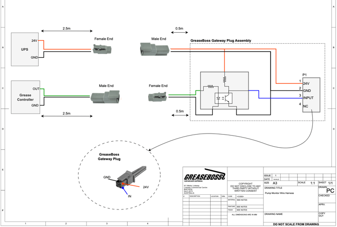
WIRING DIAGRAM